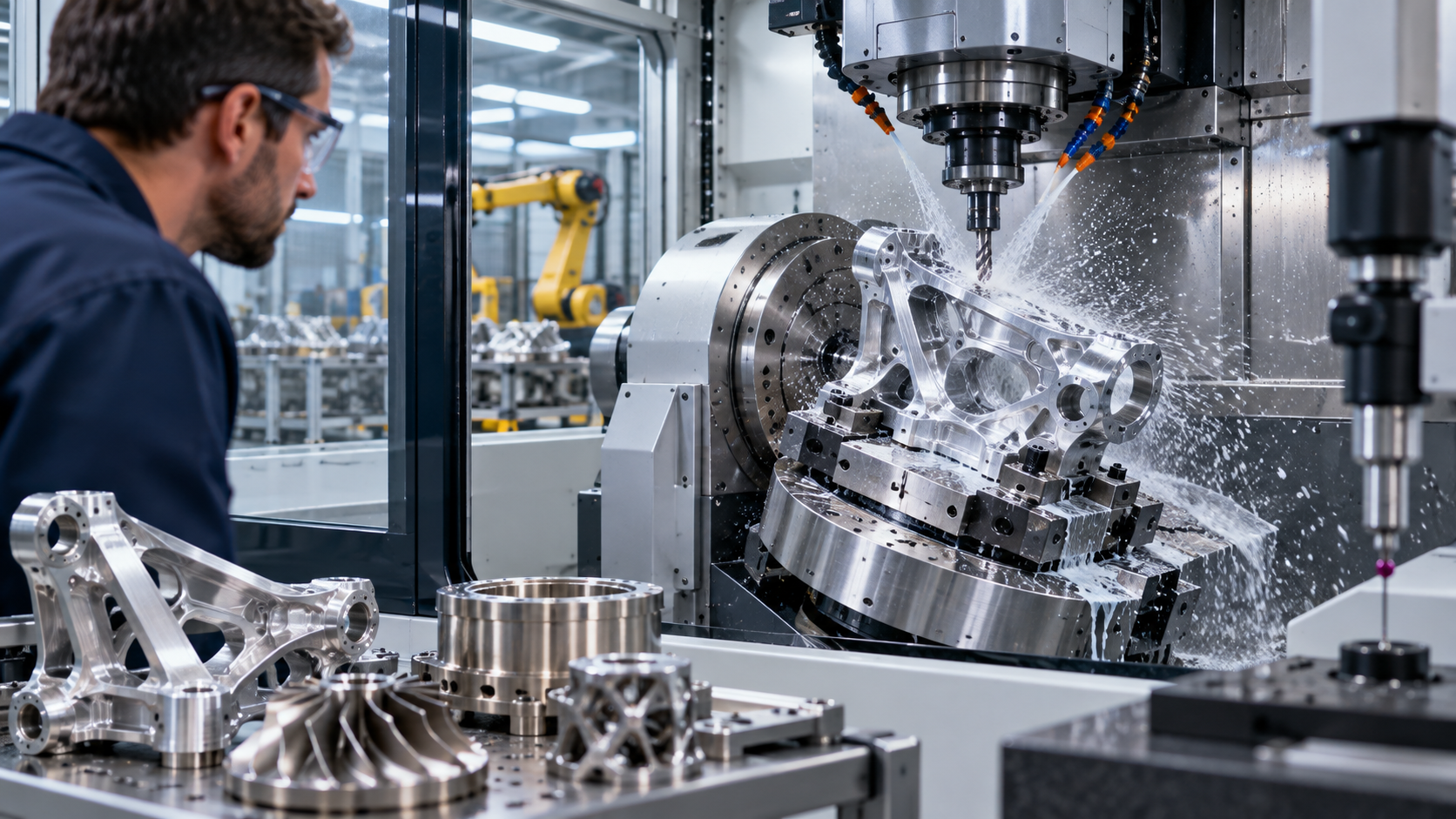
5-axis CNC high-precision machining: How Modern Manufacturers Produce Complex Parts With Greater Accuracy
5-axis CNC high-precision machining allows manufacturers to cut complex components from multiple directions while reducing the number of times a workpiece must be manually repositioned. A five axis machining centre combines three linear axes with two rotary axes, allowing the cutting tool and workpiece to be oriented for difficult surfaces, angled holes, deep cavities and multi sided features. When machine calibration, tooling, workholding, programming and inspection are controlled correctly, the process can improve consistency while making geometries that would be far more difficult to manufacture through conventional three axis methods.
Five axis technology is widely associated with demanding industries because modern components increasingly combine complex geometry with strict dimensional and surface requirements. However, owning a five axis machine does not automatically guarantee precision. Reliable results depend on the complete manufacturing process.
Understanding how five axis systems operate, where their advantages come from and what influences accuracy is essential for engineers, buyers and manufacturers evaluating precision machining.
What Is 5-axis CNC high-precision machining?
Five axis CNC machining uses three conventional linear movements, normally X, Y and Z, along with two rotary movements.
Depending on machine architecture, the rotary motion may come from the table, spindle head or a combination of both.
ISO 10791 describes five axis machining centres as machines using three orthogonal linear axes together with one or two rotary axes. The standard also recognises different machine configurations, including rotary axes on the workpiece side, rotary axes in the spindle head and combinations of swivelling heads and rotary tables.
The additional rotary movement allows a cutting tool to approach a component from many different orientations.
This is particularly valuable when parts contain features on several faces.
How Five Axis Movement Works
A conventional three axis machining centre moves along:
- X axis for side to side movement
- Y axis for front to back movement
- Z axis for vertical movement
Five axis machines add two rotary directions.
These are commonly identified as A, B or C depending on the machine configuration.
The exact axis arrangement is less important to the customer than understanding what the machine can achieve.
Haas explains that universal machining centres can use rotary positioning for both 3 plus 2 machining and simultaneous five axis motion. Its machines use dual axis rotary systems to orient components for access to multiple faces and complex geometry.
3 Plus 2 Machining vs Simultaneous Five Axis Machining
These terms are related but describe different cutting strategies.
With 3 plus 2 machining, the rotary axes position the component or cutting tool at a particular angle. Those rotary axes then remain stationary while machining occurs using X, Y and Z movement.
Autodesk describes this as positional five axis machining and notes that it is useful for angled holes, multiple sides and difficult features while reducing the number of setups.
Simultaneous five axis machining is different.
All five axes can move together while material is being removed.
This capability is useful for smoothly changing surfaces such as turbine blades, impellers, moulds and complex aerospace profiles.
Why 5-axis CNC high-precision machining uses both strategies
Simultaneous machining is not automatically required for every feature.
A precision component may use 3 plus 2 operations for drilled holes, pockets and flat faces, then use simultaneous motion only for surfaces requiring continuously changing tool orientation.
The best process is therefore the one that produces the required geometry reliably and efficiently rather than simply using all five axes at every opportunity.
7 Top Proven Tips for Better Five Axis Machining
High precision results depend on much more than the number of axes available.
The following seven principles are central to successful multi axis manufacturing.
1. Choose the Correct Five Axis Machining Strategy
The first step is deciding whether the part genuinely requires simultaneous five axis movement.
3 plus 2 machining can often produce complicated prismatic components with fewer setups while remaining easier to program.
Simultaneous machining becomes particularly valuable when surfaces change continuously or when maintaining tool orientation is important.
Autodesk notes that simultaneous five axis machining allows continuous control of the tool along complex surfaces, while 3 plus 2 machining fixes the tool orientation before performing conventional three axis cutting.
When 3 Plus 2 Machining Makes Sense
Common applications include:
- Angled holes
- Multi sided housings
- Pockets on several faces
- Port features
- Fixture reduction
- Machining around obstructions
A part that previously needed several fixtures may be positioned to multiple orientations while remaining clamped once.
That can reduce setup related variation.
When Simultaneous Five Axis Machining Is Better
Continuous movement becomes more useful for:
- Impellers
- Turbine blades
- Complex mould surfaces
- Aerospace structures
- Organic contours
- Deep curved cavities
The goal is to maintain favourable tool orientation while following the surface.
2. Reduce the Number of Part Setups
Every time a component is unclamped and moved to another fixture, another opportunity for alignment error is introduced.
Five axis machining can reduce this problem by accessing more surfaces while the component remains in the same workholding.
Haas states that five axis machining can reduce the number of setups and improve accuracy for multi sided and complex parts.
Why Fewer Setups Can Improve Consistency
Consider a component that must be machined on five different faces.
On a conventional machine, the operator may need to relocate the component repeatedly.
Each repositioning requires another datum location and clamping operation.
A five axis system may allow most of those features to be created from a single reference setup.
This helps maintain relationships between holes, surfaces and profiles.
However, fewer setups do not remove the need for accurate workholding.
The fixture must still locate the part securely and resist machining forces.
3. Control Machine Kinematics and Calibration
High precision five axis machining depends heavily on the geometric relationship between linear and rotary axes.
Small errors in rotary axis position can affect tool location as the table or spindle changes angle.
Siemens explains that relevant five axis errors can include axis misalignment, angular errors and displacement errors. Its 5X Analyzer system is designed to measure and compensate for these geometric deviations.
Renishaw similarly notes that angular positioning and axis alignment errors can negatively affect components produced on five axis machines.
Rotary Axis Accuracy Matters
The farther the cutting point is from the centre of rotary motion, the more important angular accuracy can become.
This is one reason machine calibration is an ongoing quality requirement rather than a one time commissioning task.
A precision machining company may monitor machine geometry through:
- Rotary axis calibration
- Laser measurement
- Probing cycles
- Ball bar testing where appropriate
- Reference artefacts
- Scheduled verification
Calibration procedures depend on the machine, control system and required tolerance.
Standards for Five Axis Accuracy
ISO 10791 Part 6 addresses the accuracy of speeds and interpolated paths involving linear and rotary axes.
The 2014 edition was reviewed and confirmed by ISO in 2026, meaning it remains current.
ISO 10791 Part 7 covers accuracy testing using finished test pieces and includes a freeform test component intended for five axis machining assessment.
These standards reinforce an important point: five axis precision must be measured and demonstrated rather than assumed.
4. Use Short, Rigid Cutting Tools Where Possible
Tool rigidity strongly influences machining performance.
Long tools can flex more easily under cutting forces.
Five axis orientation often allows a machine to approach a feature more directly, reducing the need for excessive tool length.
Autodesk identifies the ability to use shorter and more rigid tools as one advantage of positional five axis machining.
This can support:
- More stable cutting
- Reduced vibration
- Better tool life
- Improved surface quality
- More predictable dimensional results
Toolholder Selection Also Matters
Precision does not stop at the cutting tool.
The spindle, toolholder, collet and cutter form one mechanical system.
Runout should be controlled.
Toolholders should be clean and maintained.
Cutting tools should be suitable for the material being machined.
A high precision machine cannot compensate for a damaged holder or worn cutting edge.
How 5-axis CNC high-precision machining improves tool access
Tilting the workpiece or cutting tool can improve access to deep cavities and difficult surfaces.
Instead of extending a cutter far from the holder, the machine may orient the part so a shorter tool reaches the same feature.
This can improve stiffness while also creating better clearance between the spindle and workpiece.
5. Build Stable Workholding and Datum Strategies
A precision machining process needs repeatable workholding.
The fixture must hold the component securely without creating unwanted distortion.
Thin wall components can be particularly challenging because excessive clamping force may change their shape.
When the clamps are released, the part may move.
Good Five Axis Fixtures Provide Access
A fixture should expose as much of the component as practical while maintaining rigidity.
Five axis workholding often uses:
- Low profile vises
- Dovetail fixtures
- Zero point systems
- Custom fixtures
- Tombstones
- Dedicated locating systems
The exact method depends on material, geometry and production volume.
Datum Selection Matters
The manufacturing datum should support accurate programming, setup and inspection.
A consistent coordinate strategy helps connect:
- CAD model
- CAM program
- Machine setup
- Probe measurements
- Inspection reports
This becomes particularly valuable when producing parts with geometric dimensioning and tolerancing requirements.
6. Use CAM Simulation Before Cutting
Five axis programming creates more potential movement than conventional three axis milling.
That creates additional opportunities for collisions between:
- Tool and part
- Holder and part
- Spindle and fixture
- Machine structure and workpiece
- Rotary table and cutting assembly
Simulation is therefore a major part of reliable five axis manufacturing.
Autodesk describes machine simulation as a way to identify collisions and axis travel problems before the actual machining process begins.
Simulate the Complete Machine
Toolpath simulation alone may not be enough.
A machine aware simulation should ideally represent:
- Cutting tool
- Toolholder
- Workpiece
- Fixture
- Rotary axes
- Machine limits
- Spindle geometry
This provides a better representation of real movement.
Tool Centre Point Control
Modern five axis controls may provide functions that maintain the programmed cutting point while rotary axes move.
Haas refers to this as Tool Center Point Control and combines it with Dynamic Work Offsets in its five axis control environment.
Exact terminology varies between control manufacturers, but the principle is valuable: the control accounts for machine kinematics so the cutting tool follows the intended path as orientation changes.
7. Inspect Parts and Document the Process
Precision should ultimately be demonstrated on the finished component.
Inspection can include measurements performed both on the CNC machine and in a dedicated quality environment.
Possible equipment includes:
- Coordinate measuring machines
- Optical measuring systems
- Surface roughness instruments
- Height gauges
- Micrometers
- Bore gauges
- Machine probing systems
The correct inspection method depends on the drawing and tolerance.
In Process Probing
Probing can help establish part position, check features and support process control.
Autodesk notes that modern CNC workflows can integrate probing for part alignment and measurements during or after machining.
However, in machine probing does not automatically replace independent final inspection when customer or quality system requirements demand it.
Document Critical Characteristics
Traceable manufacturing may include:
- Inspection reports
- Material certificates
- Tool records
- Machine calibration records
- Process instructions
- First article documentation
- Nonconformance records
This is especially important in regulated or safety critical industries.
What Determines the Accuracy of Five Axis CNC Machining?
Accuracy is not determined by the CNC machine alone.
Several variables interact during machining.
Machine Geometry
Linear positioning, rotary positioning, squareness and kinematic relationships all influence tool location.
Thermal Stability
Machines change dimension slightly as temperature changes.
Spindles, ballscrews, frames and workpieces can all respond to heat.
Precision processes may use controlled warmup routines, coolant temperature management or temperature controlled production areas depending on requirements.
Cutting Forces
Aggressive cutting can deflect tools, fixtures and workpieces.
Roughing and finishing strategies should account for this.
Tool Wear
Cutting edges gradually wear.
A worn cutter can affect size and surface finish.
High precision production therefore requires sensible tool monitoring and replacement practices.
Material Behaviour
Different metals respond differently to machining.
Aluminium, titanium, stainless steel and nickel alloys each have different cutting characteristics.
Residual stress in raw material can also cause movement as material is removed.
High Precision Does Not Mean One Universal Tolerance
A common mistake is asking how accurate five axis machining is without defining the part.
There is no single tolerance that applies to every five axis component.
Achievable tolerance depends on:
- Part size
- Geometry
- Material
- Machine capability
- Fixture design
- Tool length
- Surface requirements
- Inspection method
- Environmental conditions
A responsible machine shop should review the engineering drawing before confirming tolerance capability.
Blanket promises about extremely tight tolerances across every feature and material should be treated carefully.
Benefits of 5-axis CNC high-precision machining
The main advantage is not simply that the machine has two extra axes.
The real value comes from what those axes allow manufacturers to change in the process.
Fewer Operations
Parts can often be completed with fewer setups.
This can reduce handling and intermediate fixture requirements.
Access to Complex Geometry
Tool orientation can be adjusted to reach features that would otherwise require special fixtures, extended tooling or additional machines.
Improved Surface Machining
Continuous tool orientation can help maintain favourable cutter contact on curved surfaces.
This is particularly useful in mould, turbine and aerodynamic component manufacturing.
Shorter Cutting Tools
Approaching the component at a better angle can reduce tool overhang.
Shorter tools are generally more rigid.
Better Feature Relationships
Creating more features from one setup can help maintain positional relationships between those features.
Materials Used in Five Axis Precision Machining
Five axis machines can process a broad range of machinable materials.
Common examples include:
- Aluminium alloys
- Stainless steels
- Tool steels
- Titanium alloys
- Nickel based alloys
- Copper alloys
- Engineering plastics
The correct cutting parameters, tool material, coolant strategy and machine configuration depend on the workpiece material.
Aluminium
Aluminium is widely machined because it can support high material removal rates and is used extensively in aerospace, automotive and industrial products.
Titanium
Titanium offers useful strength and corrosion resistance but can create more demanding cutting conditions.
Toolpath planning and heat management become important.
Nickel Alloys
Nickel based materials used in high temperature applications can be difficult to machine and may require rigid machines, specialised tooling and conservative process planning.
Industries That Use Five Axis Precision Machining
Five axis technology is valuable wherever complicated shapes and demanding dimensional requirements occur.
Aerospace
Applications can include:
- Structural components
- Impellers
- Turbine related components
- Engine parts
- Complex brackets
Haas specifically identifies large airframe components and complex structures as applications for its five axis machining platforms.
Medical Manufacturing
Five axis processes can support complex surgical tools, instrument components and certain implant related geometries where appropriate manufacturing and regulatory systems are in place.
Automotive and Motorsport
Applications may include:
- Cylinder heads
- Prototype components
- Suspension parts
- Moulds
- Performance components
Haas offers dedicated five axis machine configurations specifically intended for applications such as cylinder head machining.
Mould and Die Manufacturing
Five axis movement is particularly useful for contoured surfaces and deep features that would otherwise need long tools or several setups.
How to Choose a Five Axis Precision Machining Supplier
Customers should evaluate more than machine availability.
A shop may own modern equipment but still lack the process controls required for a demanding component.
Ask about:
- Machine capability
- CAM software
- Inspection equipment
- Calibration practices
- Materials experience
- Workholding design
- Quality procedures
- Production capacity
- Traceability requirements
Request a Drawing Review
The supplier should review the engineering drawing and CAD model before confirming feasibility.
Important topics include:
- Critical tolerances
- Surface finish
- Datum structure
- Inspection requirements
- Material
- Quantity
- Heat treatment
- Coatings
- Difficult to access features
Early manufacturing feedback can sometimes identify features that unnecessarily increase cost without improving component function.
Frequently Asked Questions
What is 5-axis CNC high-precision machining?
It is a CNC process using three linear axes and two rotary axes to machine complex components from multiple orientations while maintaining controlled dimensional accuracy.
What is the difference between 3 plus 2 and simultaneous five axis machining?
3 plus 2 positions the rotary axes before three axis cutting begins, while simultaneous machining moves linear and rotary axes together during the cutting process.
Why can five axis CNC machining improve part accuracy?
It can reduce the number of setups needed, helping minimise errors introduced when a part is repeatedly unclamped, repositioned and referenced.
What parts are suitable for five axis CNC machining?
Complex aerospace parts, impellers, moulds, medical components, multi sided housings and parts with angled or difficult to reach features can be suitable applications.
Does a five axis machine automatically guarantee tight tolerances?
No. Final accuracy also depends on calibration, tooling, workholding, temperature, material behaviour, cutting forces, programming and inspection.
How is five axis machining quality verified?
Manufacturers may use calibrated machine tools, probing, coordinate measuring machines, dimensional gauges, surface inspection and documented quality procedures appropriate to the drawing.
Conclusion
5-axis CNC high-precision machining gives manufacturers greater control over complex components by combining multi direction access with fewer part setups and advanced toolpath strategies. Reliable results still depend on machine calibration, rigid tooling, stable workholding, accurate CAM programming and appropriate inspection. When these elements are managed together, five axis manufacturing can produce challenging geometries efficiently while supporting the dimensional consistency required by demanding engineering applications.