Is Your CNC Shop Ready for More Repeatable Part Checks?
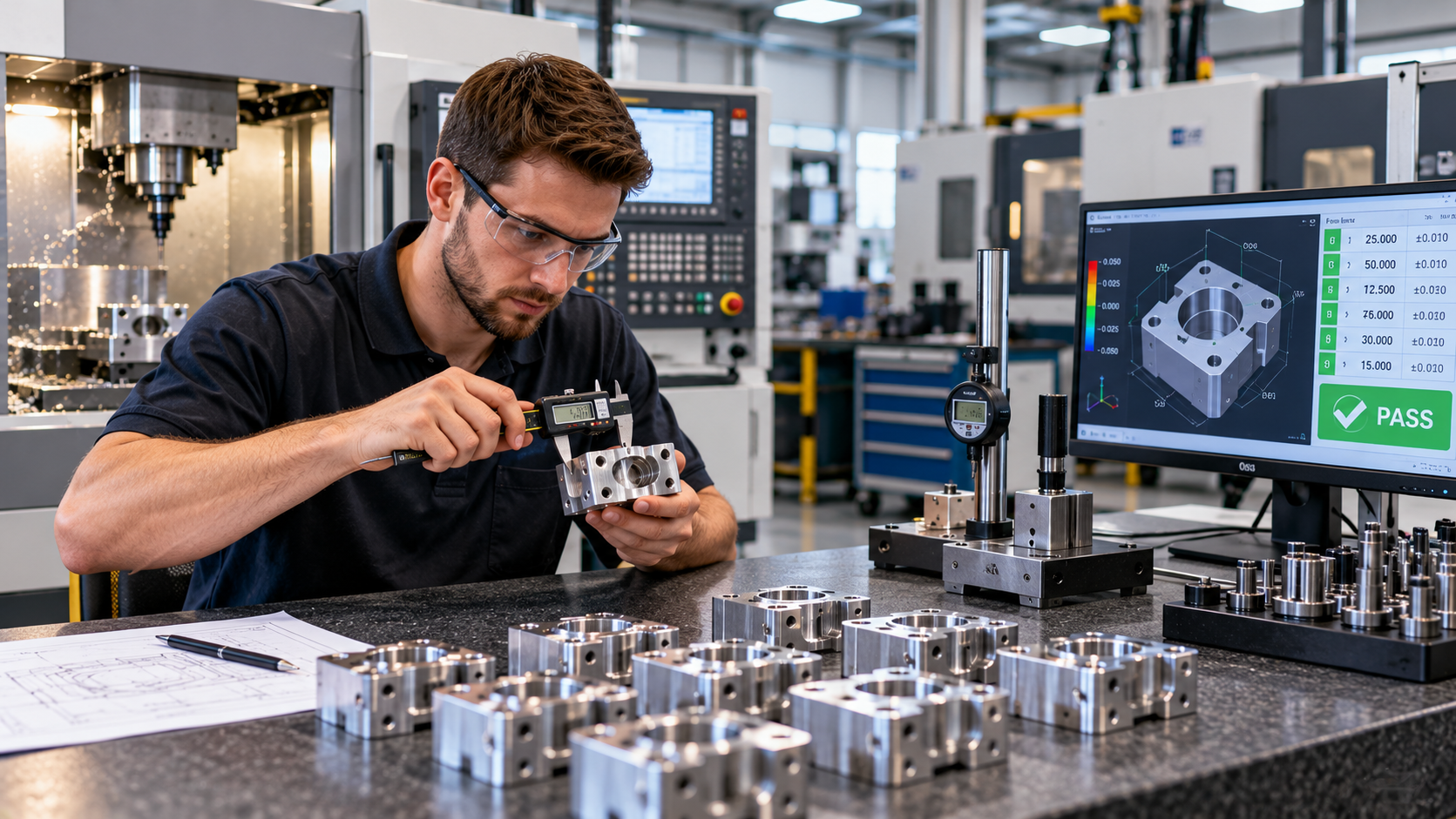
A part passes inspection on one shift, then produces a different reading on the next. Before changing a machining offset, it helps to ask whether both checks used the same method. Differences in positioning, cleanliness, measuring pressure, or instrument selection can make inspection results difficult to compare.
Tools such as pin gauges can support consistent hole checks when they match the drawing requirements and follow a defined procedure. However, dependable inspection takes more than choosing an instrument. The workpiece, reference surfaces, acceptance criteria, and recording method all influence whether the results are useful.
Repeatable part checks begin with a process another trained person can follow. Define what to measure, how to position the component, and where to record the result. Then connect that inspection information to the correct part or batch. Those habits help your shop investigate differences and make better decisions about finished work.
Use Consistent References for Height and Hole Inspection
Start with the current drawing. Confirm the part number, revision, units, tolerances, and applicable datum references before inspecting anything. A measurement only answers the intended question when its setup matches the requirement. Measuring from a convenient surface may produce a consistent number while failing to verify the specified dimension.
For height checks, identify the surface that supports the part and establish how the component should be oriented. Include any required fixtures or supports in the inspection instructions. If the workpiece rocks, tilts, or rests on an unintended feature, the reading may change each time someone positions it.
Cleanliness is part of that setup. Chips, dirt, and burrs can prevent proper seating on a surface plate or fixture. Clean the supporting face and inspect it for damage before measuring. Follow the specified deburring procedure rather than removing material casually from an edge that may have a dimensional requirement.
Check the instrument according to its operating instructions and your shop’s verification procedure. Confirm the reference setting and inspect contact surfaces for contamination or damage. A quick zero check can reveal some problems, but it does not replace calibration or verification across the instrument’s working range.
For suitable vertical measurements, height gauges provide a way to inspect accessible features from a reference surface. Use the appropriate contact and controlled measuring force. Record how the feature is contacted when different approaches could produce different readings, especially on curved or narrow surfaces.
Temperature also deserves attention where tolerances are close. Recently machined parts may still be warm, and handling can transfer heat. Follow the shop’s procedure for stabilizing parts and equipment before final acceptance. Consistent environmental conditions help reduce differences that could otherwise be mistaken for changes in the machining process.
Hole inspection requires equally clear instructions. Specify the hole being checked, its permitted limits, and the appropriate gauge sizes or measuring equipment. A fit check can provide useful acceptance information, but it does not produce the same information as a measured diameter. Choose the method that suits the actual requirement.
For a defined go/no-go procedure, account for gauge tolerances and the applicable acceptance rules when selecting gauges. Clean the hole and gauge, check for interfering burrs, and never force entry. A gauge that encounters resistance needs careful interpretation; it should not become an invitation to push harder until the part appears acceptable.
Remember that size, location, and geometry are separate requirements. A hole may accept a size gauge while being positioned incorrectly relative to another feature. Include additional inspection methods where the drawing requires them. Clear procedures help operators understand both what a check establishes and what still needs verification.
When two inspectors disagree, compare their setups before changing the part or program. Review orientation, instrument condition, contact technique, and environmental conditions. For critical characteristics, a structured measurement-system study can help evaluate variation between repeated checks and different operators. The goal is to understand the inspection process well enough to trust its results.
Keep Part Identification Connected to Your Inspection Records
Reliable measurements lose value when nobody can tell which component they describe. A spreadsheet row or inspection sheet needs a dependable connection to the physical work. Establish that connection early enough to preserve it through machining, outside processing, final inspection, and packaging where those stages apply.
The appropriate level of identification depends on the job. A batch number may suit components handled together, while individual serial numbers may be necessary when each piece requires its own history. Follow customer requirements and your production system rather than assigning more detail than the workflow can maintain accurately.
Define the information each record needs. Depending on the application, that may include the part number, drawing revision, batch or serial identifier, inspection date, instrument identification, results, and acceptance status. Keep entries clear enough that another person can understand what was checked without reconstructing the job from memory.
Distinguish numerical measurements from attribute results. A recorded diameter communicates something different from a pass/fail gauge check. Include units with measured values and identify the relevant characteristic. Avoid recording a simple “good” when the procedure requires an actual measurement or a specific acceptance result.
Inspection status should remain visible as parts move. Separate accepted pieces from work awaiting inspection, correction, or disposition. Temporary labels, controlled containers, or other suitable methods can maintain identity before permanent marking. When a part is reworked, preserve its record and document the required reinspection rather than treating the earlier result as current.
If permanent identification is specified, confirm its content, location, and timing. Marking may interact with coatings, surface finish, or critical features, so include it in the process plan. Verify that the identifier applied to the component matches the inspection record before the part moves forward.
A fiber laser engraving machine may support permanent identification when its capabilities suit the material and marking specification. Validate the process, follow equipment instructions, and check the completed identifier for accuracy and readability. For variable information, control the data entry or transfer process to reduce duplicate or mismatched identifiers.
More repeatable part checks come from consistent references, suitable instruments, clear methods, and reliable records. Start with one important feature and make its inspection process easy to reproduce. Then maintain the connection between each result and the work it represents. That foundation helps your shop resolve disagreements sooner and release parts with greater confidence.